
Star Cement Silo
-
Clinker Silo Condition Assessment & Thermal Modeling
- Location: Ras Al Khaima, UAE
Project Description
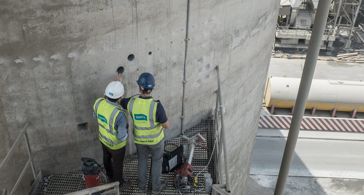
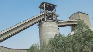
The Clinker Silo at Ras Al-Khaimah cement plant is an existing structure constructed in 2008 and it consists of a 13.5m diameter reinforced concrete shell, 29.7m high with 0.25m shell thickness.
The Silo initially was intended and designed to serve as a reject clinker silo, where the clinker would be cooled-down prior to entering the silo at temperatures around 80-90°C. However, due to an increase in the plant production capacity but not as much in the cooling capacity, the clinker now enters the silo at temperatures estimated in the range of 180 – 220°C.
The Client’s main concern is the damage potentially affecting the 250mm-thick wall of the silo due to internal exposure to elevated temperature and damage caused due to elevated temperatures or significant temperature gradients between the inner and outer faces
During the previous silo shutdown, a visual assessment of approximately 15 – 20% of the external silo has been performed by in-house maintenance team from the exterior staircase and revealed no apparent signs of damage, however, time constraints did not allow them to visually assess the situation from the inside of the silo.
Client Objective
- Characterize the concrete of the silo wall;
- Determine the nature and extent of deterioration (cracking, delamination, corrosion, etc.) of the structure;
- Determine the presence of active or potential degradation mechanisms;
- Evaluate damage potentially affecting the silo wall due to the temperature gradient between internal and external face.
SIMCO Solutions
A phased approach was proposed, including a thermal numerical modeling allowing limited intrusive field investigation. The key to SIMCO’s approach was to confirm whether the temperature gradient between the internal face of the silo shell and external surface could cause any distress (cracking) on the silo shell.
Documents Review – Review and analyze documents provided by the client with the aim to ascertain;
- Design and as-built details
- The original material characteristics, (concrete and reinforcement grade, concrete mix details, etc.), Type of structure, details of construction, any modifications made at later stages including details of repairs carried out, if any.
- Any historical inspection/testing data available for the structures under consideration.
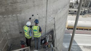
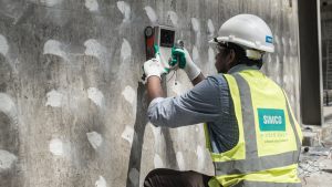
Field investigation – A testing program was elaborated and condition assessment activities combination of NDTs & SDTs in accordance with “ASTM” and “BS EN” were planned to;
- To record the visual defects and damages
- Asses the quality of concrete
- Check the quality of steel and corrosion potential of steel
- To Collect the samples for lab testing
Laboratory Testing – Laboratory tests in accordance with “ASTM” and “BS EN” were conducted on concrete cores extracted during the field operations. The laboratory test results complement the field observations in terms of properties and/or current contamination. Laboratory tests include;
- Compressive strength
- Petrographic Examination
- Total Chloride and/or Sulfate Ion Contamination Profiles
- Carbonation Depth
Results – Repair Strategies for Observed Defects
Internal Face of Silo Shell
The internal face of silo shell (above +10.8m) requires a refractory lining (50mm thick) suitable for high-temperature applications, containing high purity refractory cement as the refractory binder. This will prevent temperature differential across thickness of silo wall preventing further cracking and will reinstate rebar cover on internal surfaces.
External Face of Silo Shell
Crack Injection
All cracks on the external surface that are wider than 0.2mm are required to be repaired by injection. In case the injections are planned to be carried out before application of internal lining, micro-cement shall be used as injection material as generally epoxy resins will soften under high heat, usually around 70°C. Injections after application of lining can be done by use of epoxy resin.
Repair of Hollow Sounding Patches
All identified patches of hollow sounding shall be repaired after removal of loose honeycombed concrete ensuring minimal damage to the rest of the concrete thickness. The honeycombed/loose concrete shall be broken back by handheld concrete and can be reinstated by hand applied proprietary mortar.
Application of Cementitious Coating
After injections of cracks (wider than 0.2mm) and patch repairs, the external face of silo shell shall be coated with a cementitious coating to cover fine cracks.
Silo Roof Slab Top
Crack Injection
All cracks on slab top shall be repaired as detailed below:
- On both sides of the crack, the side edges will be slightly chiseled to give a V-shape. If required do chiseling until a hard concrete is encountered.
- Remove loose material from the crack area and blow out the dust and debris from the gap of crack by using a compressor or air blower.
- Drill holes in slab surface in the line of crack up to a depth of about 100mm & 10 mm diameter @ 300 – 400 mm c/c
- Install appropriate packer into the hole and fill the top of the V-grove portion by appropriate Epoxy modified mortar.
- Flush all cracks with water and after removal of water from cracks pressure inject cracks with microfine cement by starting from first in the middle nozzle from one side of the crack. Continue till it is forced out of next nozzle.
Application of Polyurea Coating
After completing all injection works, the top surface of the slab can be coated with a 2mm thick polyurea coating.